STRUCTURAL
PRE-INSTALLATION VERIFICATION
PRE-INSTALLATION VERIFICATION
Per AISC/RCSC section 7 Pre-Installation verification, fastener assembly testing must be conducted, onsite, by the installation crew, using actual installation tools. Contrary to popular opinion Pre-Installation Verification testing DOES NOT pass or fail fastener assemblies. Testing is intended to discover possible issues between fasteners, tools and installers, before field bolting operations commence.
The next few sections describe issues that may be highlighted by Pre-Installation testing results.
Fasteners:
Are the fastener assemblies capable of achieving 105%, or more, of minimum required bolt pretension at all?
Torque must be applied to the fastener assembly until the bolt tension measurement device indicates adequate pretension or the bolt fails, whichever occurs first. Failure occurs by either the bolt breaking before minimum pretension, or tensile load climbs and then falls, as indicated by the bolt tension measurement device, without ever achieving minimum pretension. Except for TC bolts1, applying additional lubricant may alleviate failure. However, if additional lubricant solves bolt failure, all fasteners represented by lubricated test samples, must be similarly lubricated.
Tools:
Do the installation tools have enough output torque to tighten adequately lubricated fastener assemblies, to at least 105% of minimum required pretension?
If the full effort of an installation tool applied to a fastener assembly, does not result in at least 105% of required minimum pretension, the tool must be replaced for testing as well as for installation. While not always true, an adequate installation tool should have a drive chuck at least as large as the fasteners being tightened. For example; when tightening ¾” bolts, the installation tool should have a square drive chuck of ¾” or more. Also, a tool’s manual may claim a higher output torque than the tool can produce. Such claims are usually stated vaguely, such as, claiming the tool’s motor can produce some high amount of torque. This statement may describe no-load torque output but once load is applied, the high torque described will not be realized.
Installation crews:
Do the installers understand how to employ the selected method?
The installers must understand that a snugged tightened condition must be achieved before the pretensioning method is employed. Once a snug condition exists, the installers must fully understand the method they employ and not confuse, or combine, fundamentals of individual methods. Such as applying a torque value to rotate the nut to turn angle listed for Turn-Of-Nut or employing a torque wrench as an inspection technique after the turn is complete. Doing so combines elements of Calibrated Wrench and Turn-Of-Nut. In the same fashion, inspecting a DTI installation with a torque wrench combines DTI and Calibrated Wrench methods.
Snug-tightened Joints
Every bolted joint must be snug-tightened before a pretensioning method can be performed. Snug-tighten is defined as the effort applied to bring the steel plies into firm contact. AISC/RCSC describes the effort as the full effort of an ironworker or a few impacts of an impact wrench (section 8.1) until the nut cannot removed by hand. An attempt at manual nut removal is the only requirement for inspection (section 9.1). There is no pretension requirement for a “snugged” joint. Per AISC’s Specification for Structural Steel Buildings (360) Section J3:
“There are no specific minimum or maximum tension requirements for snug-tight bolts.”
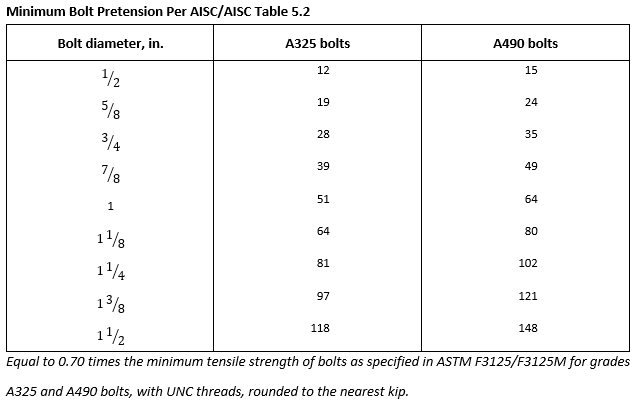
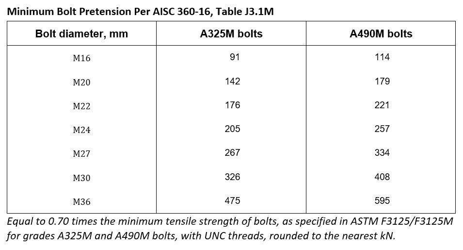
The snug-tight condition is critical for the Turn-Of-Nut method since it relies on the snug position as its starting point. With only hand tight as the inspection criteria, Snug-tight may begin with a pretension that is negligible or zero. If so, the turn listed in table 8.1 may result in less than minimum required pretension to comply with AISC table 5.2.
Conversely, snug-tightening may result in a pretension near or greater than the minimum required, and the required turn may strip or break the bolt when employed. This is especially true of bolt diameters ¾” and below.
Snug-tightening does not affect the success of other methods. Calibrated wrench, DTIs, and TC bolts do not use a snug position a starting point. If aggressive (high snugging) occurs, these methods will alert those involved aggressive snugging has occurred. A DTI will flatten, a TC bolt will shear, or a calibrated wrench will not advance the nut/bolt during the pretensioning operation. If low snugging occurs, the same three methods will work as designed. The DTI and TC bolt will remain intact and a Calibrated Wrench will continue to tighten until the stall torque is reached.
Verification Basics
The following content applies to AISC/RCSC Pre-Installation testing only. Individual projects, State DOTs and Federal Highway specifications may differ substantially and will not be covered here. The following represents Applied Bolting Technology’s interpretation of Pre-Installation testing based on The Research Council on Structural Connections’ Specification for Structural Joints Using High-Strength Bolts (AISC/RCSC 348) and The American Institute Steel Construction’s Specification for Structural Steel Buildings (AISC 360). Anyone interested in a different interpretation is welcome to read the documents themselves.
Verification testing can be summarized as snug-tightening, at least three sample fastener assemblies, in or with, a bolt tension measurement device, applying the selected pretensioning method, and confirming at least 105% of minimum required pretension has been achieved. While each method accomplishes this with different tools, fastener components, or tightening techniques, all 4 tensioning methods follow these basic principles of snug fastener, apply method, and verify conformity to specification. Lastly, all acceptable methods are expected to permanently deform the fastener into its inelastic region2.
Sampling
Pre-Installation verification testing begins with sampling. Per AISC/RCSC section 7.2:
“On a sample of not fewer than three complete bolting assemblies of each combination of diameter, length, grade, and lot to be used in the work; Using bolting assemblies that are representative of the condition of those that will be pretensioned in the work” (RCSC 16.2-52)
Regardless of method, it is critical that assembly samples be TRULY REPRESENTATIVE, that is, in similar condition as fasteners being actively pretensioned. Testing a “new” fastener, removed directly from sealed shipping receptacles, does not constitute a representative sample, unless only new condition fasteners are actively being pretensioned.
Fasteners that have been snug-tightened & exposed to the weather, for any amount time, must be verified as is, if this condition accurately represents the fasteners’ being tightened in the steelwork. TRULY REPRESENTATIVE samples are especially important for TC bolts and Calibrated Wrench installation and testing because these methods are negatively affected by weathering and lubrication degradation.
Turn of Nut
- Place each unique configuration of sample fastener assembly in a bolt tension measurement device with washers positioned in accordance with table 6.1, if necessary, and section 6.2.
- Snug the fastener in accordance with AISC/RCSC section 8.1 and inspect per section 9.1.
- Apply the appropriate turn angle based on the ratio of the bolt diameter to its length (table 8.1).
- Verify the resulting pretension meets or exceeds the value in table 7.1.
- If the turn angle does not produce adequate pretension per table 7.1, continue turning until the resulting pretension meets or exceeds the minimum required bolt pretension as listed in table 7.1. Since table 8.1 permits an upper tolerance for each rotation angle/turn, it is allowable to rotate the nut beyond the value listed in the table. However, if more turn is necessary, the ACTUAL turn angle/rotation determined must be used for field bolting operations, and not table 8.1’s listed turn.
TC Bolt
- To be performed with every installation tool and repeated after any changes to the TC bolts original lubricated condition.
- Place each unique configuration of sample fastener assembly in a bolt tension measurement device with washers positioned in accordance with table 6.1, if necessary, and section 6.2.
- Snug the fastener in accordance with AISC/RCSC section 8.1 and inspect per section 9.1.
- Apply the TC Shear tool to the fastener and operate until the splined end twists off the fastener.
- Verify the resulting pretension meets or exceeds 105% of the minimum required bolt pretension as listed in table 7.1.
- If the resulting pretension does not meet the value in table 7.1, the fasteners must be returned to the manufacturer for rework and the non-compliant lot of TC fasteners must not be incorporated in the steel work. TC Bolts may not be altered or reworked by anyone but the manufacturer. It is not permissible to remedy noncompliant TC assemblies.3
Calibrated Wrench
- To be performed daily with every installation tool and repeated with any changes to the tool’s supply (adding additional air lines etc.).
- Place each unique configuration of sample fastener assembly in, or with, a bolt tension measurement device with washers positioned in accordance with section 6.2.2 and table 6.1, if necessary.
- Snug the fastener in accordance with AISC/RCSC section 8.1 and inspect per section 9.1.
- Apply the assumed torque to the nut only, with the bolt head restrained. It is not permitted to turn the bolt head.
- Verify the resulting pretension meets or exceeds the minimum required bolt pretension as listed in table 7.1.
- If the resulting pretension does not meet or exceed the value in table 7.1, increase the applied torque or clean and lubricate additional samples and reattempt all steps described here.
- Complete 3 successful tests and direct bolt tightening crews to use the highest torque value observed during testing.
DuraSquirt® DTI in accordance with AISC/RCSC 2.12.6 (no feeler gauge)
Download DuraSquirt® 2.12.6 AISC/RCSC Directions here
The following lists the steps for ASTM F959 DuraSquirt® DTIs. See here for more information.
- Place each unique configuration of DuraSquirt® DTI bolt assembly in a bolt tension measurement device with washers placed in accordance with table 6.1, if necessary, and a washer against the DTI bumps.
- Snug the fastener in accordance with AISC/RCSC section 8.1 and inspect per section 9.1.
- Tighten the fastener assembly until DuraSquirt® indication material appears at every available Squirt™ location, i.e. a 5 bump DTI has 5 available Squirt™ locations.
- Verify the resulting pretension meets or exceeds the minimum required bolt pretension as listed in table 7.1.
- If the resulting pretension does not meet or exceed the value in table 7.1, consult the advisory section of Applied Bolting Technology’s website and apply the recommendation described therein.
Additional assistance is available by directly contacting Applied Bolting Technology via email at info@appliedbolting.com or calling 800 552-1999 or 802 460-3100.
Standard DTIs & Squirter® DTIs
The following lists the steps for both Standard DTIs and Squirter® ASTM F959 DTIs. See here for more information.
- Place each unique configuration of sample fastener assembly, containing a DTI, in a bolt tension measurement device with washers placed in accordance with table 6.1, if necessary, and a washer against the DTI bumps.
- Snug the fastener in accordance with AISC/RCSC section 8.1 and inspect per section 9.1.
- Tighten the fastener assembly until the bolt tension measurement device indicates the minimum required bolt pretension as listed in table 7.1.
- Insert the appropriate feeler gauge between each available space between the DTI protrusions until the gauge physically touches the bolt shank. Each instance the feeler gauge fits between the DTI protrusions, and touches the bolt shank, shall be known as an entry. Each time the feeler gauge does not touch the bolt shank, shall be known as a refusal.
- The number of entries may not be zero. Conversely, the number of refusals may not be 100%. In other words, a DTI must not be completely flattened when the bolt tension measurement device dial reaches the minimum value listed in table 7.1.
- The number of entries/refusals defines the unique assembly’s test gap4 and Job Inspection Gap.
- Record the number of refusals as the baseline for field inspection. The number of refusals permitted in the steelwork must be more than assembly’s test gap discovered during verification. For example, if the test gap is defined as 0 refusals, out of a potential of 5, the Job Inspection Gap shall be at least one additional refusal in the steelwork.
- If the number of entries equal zero and refusal count is 100% when the bolt tension measurement device dial reaches the minimum pretension listed on table 7.1, consult the advisory section of Applied Bolting Technology’s website and apply the recommendation described therein.
Additional assistance is available by directly contacting Applied Bolting Technology via email at info@appliedbolting.com or calling 800 552-1999 or 802 460-3100.
Download a DTI Pre-installation Verification worksheet here
1 AISC 348-20, the Research Council on Structural Connections, Specification for Structural Joints Using High-Strength Bolts: Section 2.10.4 “matched bolting assemblies shall not be relubricated by anyone other than the Manufacturer”
2 RCSC 16.2-47 "In any of the foregoing installation methods, it can be expected that a portion of the bolt assembly (the threaded portion of the bolt within the grip length and/or the engaged threads of the nut and bolt) will reach the inelastic region of behavior. This permanent distortion has no undesirable effect on the subsequent performance of the bolt."
3 AISC 348-14, the Research Council on Structural Connections (RCSC), Specification for Structural Joints Using High-Strength Bolts: Section 2.2 "ASTM F1852 and F2280 twist-off-type tension-control bolt assemblies and alternative-design fasteners that meet the requirements in Section 2.8 shall not be relubricated, except by the manufacturer."
4 ASTM F959 Appendix X1. "The job inspection gap shall be a gap less than the measured DTI test gap at 1.05× the minimum required bolt tension."